Sensor Data Reporting
The MTS160 measures and reports several track and marker parameters in real time. New measurement data is generated at 200 Hz (5 ms intervals).
Continuous Dual Track Detection
The MTS160 always reports data for two tracks simultaneously: one data set for the left track and one for the right track. This is true even when only a single physical track is present. In that case, the left and right reported values are identical. This reporting method simplifies the handling of forks, merges, and intersections.
Track Detection and Strength
The sensor reports track presence and magnetic strength using two status bits:
| TS1 | TS0 | Track Detection | Magnetic Strength |
|---|---|---|---|
| 0 | 0 | No Track | — |
| 0 | 1 | Track Present | Minimal |
| 1 | 0 | Track Present | Medium |
| 1 | 1 | Track Present | Strong |
The sensor operates correctly whenever a track is detected. However, for best performance, the magnetic field should be at least medium over the full path.
TIP
If the reported strength is minimal, reduce the sensor height or use magnetic tape with stronger magnetization.
Lateral Tracks Positions
The sensor reports the lateral position of each track relative to the center of the sensor in millimeters. Positions to the left of center are negative; positions to the right are positive.
Track Incidence Angles
One of the MTS160's unique capabilities is the measure of the track's incidence with the sensor. This enables the robot to distinguish between going off track, and therefore the need to apply only small trajectory corrections and entering a curve and therefore needing to apply sustained steering.
The sensor reports the incidence angle of each track with a 1-degree resolution.

The advantages of using the angle and methods to improve track following are explained later in this document.
Forks, Merges, and Intersections
Current firmware implements explicit feature flags for forks, merges, and intersections. These are advisory detection hints derived from the magnetic geometry. Validate them on the actual tape layout before using them for route decisions.
The sensor always reports the position and angle of two tracks: a left track and a right track. This is true even when there is only one physical track under the sensor. In that case, the reported left-track and right-track values are identical.
When the robot is traveling on a single track, the sensor reports two identical track positions and two identical angle values. Assuming the robot is perfectly centered and aligned with the track, these will be 0 mm and 0 degrees.
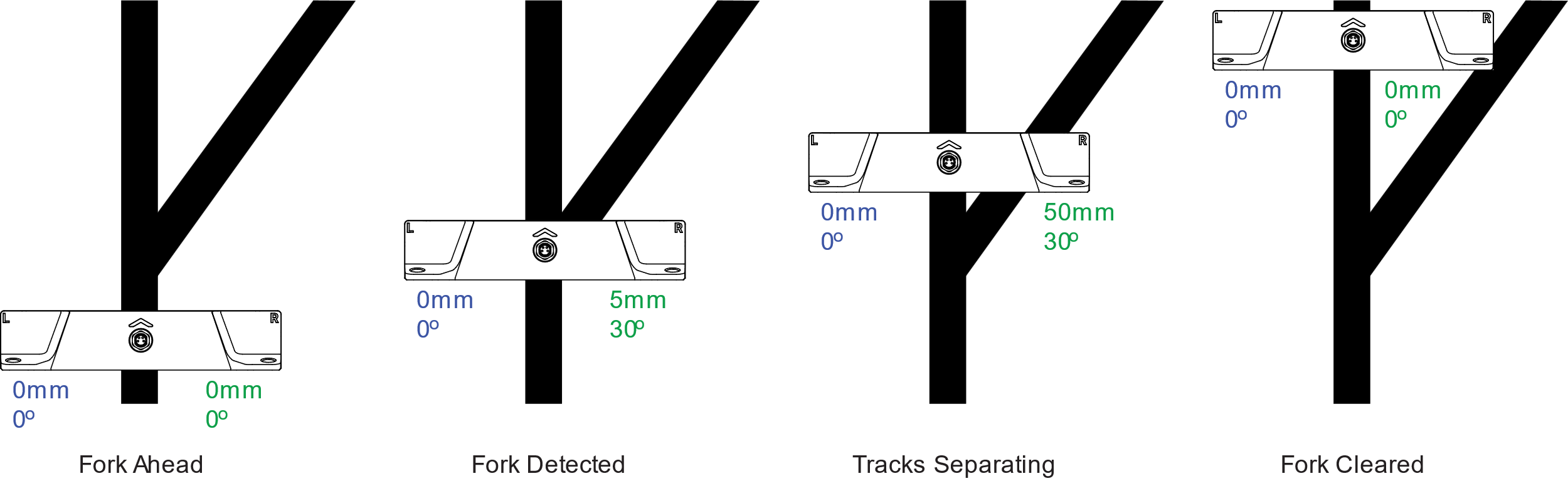
Forks
As the robot enters a fork, the second branch begins to appear within the sensing area. The sensor then reports two distinct tracks, one on the left and one on the right, each with its own position and angle.
The controller can choose which branch to follow simply by selecting either the reported left track or the reported right track.
Once the fork is passed and only one physical track remains, the left and right reported values become identical again.
The firmware sets the Fork flag when the left/right track angle difference is positive and larger than approximately 10 degrees, remains below 45 degrees, and the left/right position separation is not larger than the current magnetic tape width.
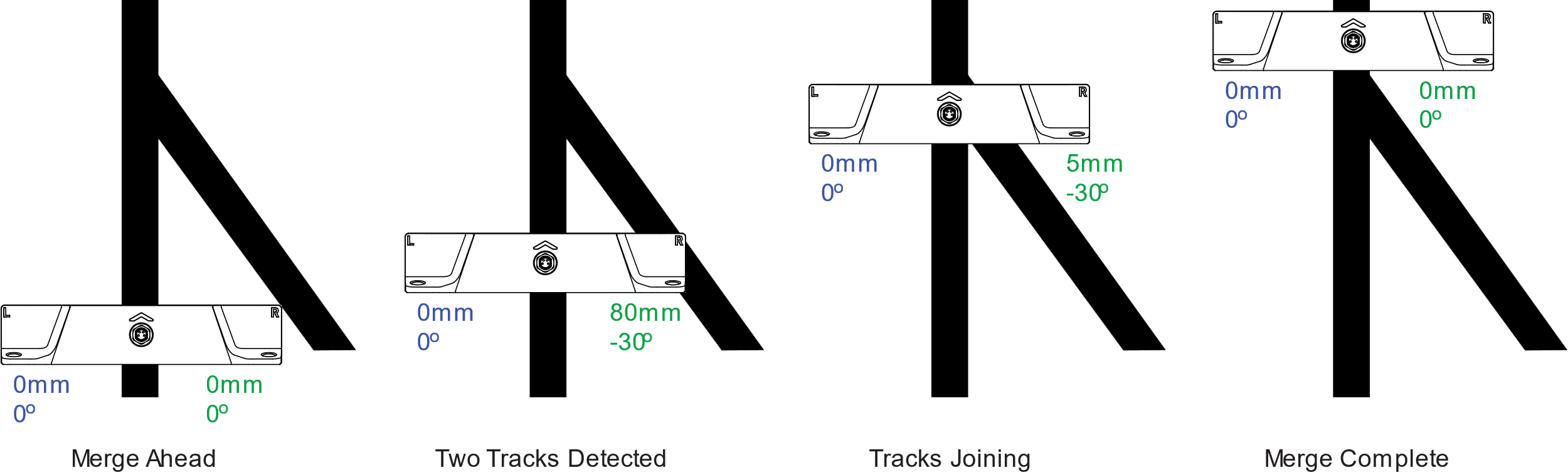
Merges
The same principle applies to merges. Before reaching a merge, the controller must already be set to follow the track corresponding to the desired path.
As the merging branch enters the sensing area, the sensor reports both tracks with a sudden large separation value. If the controller is following the correct side, the robot will continue smoothly through the merge.
After the merge is completed and only one physical track remains, the left and right values again become identical.
The firmware sets the Merge flag using the same geometry as fork detection, but with a negative left/right track angle difference larger than approximately 10 degrees in magnitude.
WARNING
Beware that if the robot is set to follow the wrong side, the robot will steer abruptly toward the incoming branch as soon as it is detected.
Intersections
The firmware treats a broad crossing or intersection as a special track feature. It sets the Intersection flag when a front or back sensor row sees a broad magnetic field where the minimum measured field is above the weak tape threshold.
During the intersection condition, marker flags are cleared and the reported track angles are set to 0 degrees. Track position is reported as the strongest detected magnetic peak if one row has a clearer peak than the other; otherwise it remains centered. Controllers should use the explicit intersection flag instead of interpreting a zero angle or centered position as a normal straight track.
Left and Right Position Markers
Markers are short pieces of magnetic material with polarity opposite to that of the main track. They are used to identify specific locations along the robot path, such as forks, merges, charging points, speed-change zones, or other reference locations.
The sensor can detect and report a left marker on the left side of the track and a right marker on the right side. Markers can also be combined into patterns to identify multiple locations uniquely.
It is recommended to use 25 mm or longer markers. Markers that are too short will not have enough surface to ensure strong adherence to the floor. Markers shorter than 25 mm may also have insufficient magnetic strength.
While markers must have a minimal length to be physically detected by the sensor, their presence will be reported to the PLC or Navigation Computer as they appear and disappear. Left and Right markers need to be longer as the robot moves faster or/and if their position is read at a lower frequency. This restriction does not apply to Navicode coded markers as these are decoded within the sensor.
It is recommended to place the markers so that their edge is 20 to 30 mm away from the edge of the main track. The sensor reports the lateral position of markers when detected.
When two markers are on the same side, spacing between them should be 50 mm for their magnetic fields to be distinct from one another.
When no guide tape is present, a standalone opposite-polarity magnetic source is reported as marker detection rather than track detection. In the common point-source case, firmware reports both left and right marker flags at the same lateral position.
Last-Millimeter Magnetic Point-Source
Another unique capability of the MTS160 is the detection of magnetic point sources with millimeter-level X and Y position reporting. By installing one magnetic disk at a known location on each side of the track, the robot's position and orientation can be determined with very high precision.

TIP
This feature makes the sensor a valuable accessory for last-millimeter positioning in robots that primarily use laser or vision navigation.
The magnetic disks must have polarity opposite to that of the main track. The sensor detects them in the same way as regular markers, while also reporting their X and Y coordinates.
Standalone point-source magnets are not decoded as Navicode. They are reported through the marker detection flags and marker X/Y position fields.
Adhesive point-source magnets are available from Naviq.
Navicode Coded Markers
The MTS160 can detect and decode specific combinations of left and right markers using a simple coding scheme. The scheme represents binary 0 and 1 using basic marker patterns that can be concatenated to form multibit values.
Decoding begins when the sensor detects a marker on either side of a detected guide track. It continues as long as markers are present on the left or right side. Decoding is completed when no marker is detected on either side, at which point the captured value is stored. Markers detected without a guide track do not drive the Navicode decoder.
A Navicode always starts with bit value 0 and ends with an end marker. These conventions allow the code to be detected correctly regardless of robot orientation or travel direction.
Navicodes can range from 1 bit to 16 bits in length. When a code is successfully recognized, its value is stored in a register that can be read through serial communication or CAN communication.
An 8-bit counter increments each time a valid code is recognized. The navigation controller or PLC can monitor this counter to detect the arrival of a new code and then read the stored code value.
TIP
A Navicode pattern generator is available on the Naviq website. This tool will create an image of the marker elements' arrangement based on a user-entered value.
Internal Sensors Self-Test
The MTS160 includes an internal self-test function for the magnetic sensing hardware. The test is performed automatically at power-up and can also be started manually through USB, RS232, or CANopen communication.
During the test, embedded electromagnets are briefly energized to generate a local magnetic field beneath the sensing elements. The MCU checks the measured response against the firmware threshold and stores an aggregate pass/fail result together with the minimum and maximum response values.
The self-test results are stored in three registers and can be read at any time through the communication interface. The reported values are:
- Pass/Fail Status: A value of 1 indicates the test passed, while 0 indicates a fail condition
- Minimum Field Difference: The smallest magnetic field change measured during the self-test, reported in microtesla
- Maximum Field Difference: The largest magnetic field change measured during the self-test, reported in microtesla
If the test fails, the result does not indicate which internal sensing element failed.

In the event of a failure, robot operation should be stopped until the cause has been investigated. Current firmware reports the failure through ?STRS and CAN object 0x2003; it does not display a separate red self-test-failure LED pattern.
The complete self-test sequence takes approximately 30 ms. During this time, ambient magnetic conditions should remain stable, so manual self-tests should be performed while the robot is stationary.