Communication Interfaces
The MTS160 supports multiple communication interfaces for integration with various control systems:
- Serial Communication (RS232)
- CAN Communication
- USB (for configuration and testing)
The MTS160 features a unique multi-interface, multi-protocol communication port that uses only two shared pins or the 4-pin connector. The choice of the protocol and interfaces are software selectable.

Serial Communication
Serial communication is the factory default mode. It operates in full duplex mode with:
- 8 data bits
- No parity
- One stop bit
- No flow control
- No command echo
Serial Protocol
The MTS160 uses a custom ASCII based serial protocol, based on a command-response model with the following structure:
| Command Prefix | Command Code | Comma Seperated Fields | Carriage Return (\r) |
where:
- Command Prefix: Indicates the type of command
- Command: 4 letter command code (not case sensitive)
- Fields: Optional values for the command
Command Prefixes
| Prefix | Type | Description |
|---|---|---|
| ! | Set | Execute actions or set configuration parameters |
| ? | Get | Request sensor data or read configuration |
| # | Repeat | Like Get, but repeats at specified interval |
| @ | Stop | Stops all running repeat commands |
Examples
For Set commands (!):
Command: !COMMAND
Response: !COMMAND,OK
For Get commands (?):
Command: ?COMMAND
Response: ?COMMAND,data1,data2,...
For Repeat commands (#):
Command: #COMMAND,interval_ms
Response: ?COMMAND,data1,data2,... (repeating)
Serial Commands Reference
Commands Overview
Action Commands
| Command | Description | Access |
|---|---|---|
| ZERO | Calibrate Zero Level | Write |
| STST | Execute Self-Test | Write |
| SAVE | Save current configuration to internal memory | Write |
| RSET | Reset to Factory Defaults | Write |
Data Request Commands
| Command | Description | Access |
|---|---|---|
| FWVR | Firmware Version | Read |
| HWVR | Hardware Version | Read |
| SNID | Sensor ID | Read |
| NVCD | Navicode Marker | Read |
| RSEN | Raw Sensor Values | Read |
| SALL | All Sensor Data | Read |
| STRS | Self-Test Results | Read |
| TWID | Tape Magnetic Width | Read |
Configuration Commands
| Command | Description | Access |
|---|---|---|
| CMCF | Communication Mode | Read/Write |
| RSCF | RS232 Configuration | Read/Write |
| CNCF | CAN Configuration | Read/Write |
| SNCF | Sensor Configuration | Read/Write |
Data Request Commands
FWVR
Description: Firmware Version
Access: Read
| Parameter | Description | Type | Format |
|---|---|---|---|
| version | Firmware Version | uint32_t | 010203 = v1.2.3 |
| build | Firmware Build | uint32_t | - |
| hash | Firmware Hash | uint32_t | - |
HWVR
Description: Hardware Version
Access: Read
| Parameter | Description | Type | Range |
|---|---|---|---|
| version | Hardware Version | uint8_t | - |
SNID
Description: Sensor ID
Access: Read
| Parameter | Description | Type | Range |
|---|---|---|---|
| id | Sensor ID | uint32_t | - |
NVCD
Description: Navicode Marker
Access: Read
| Parameter | Description | Type | Range |
|---|---|---|---|
| navicode | Navicode | uint16_t | 0-65535 |
| count | Navicode Counter | uint8_t | 0-255 |
RSEN
Description: Raw Sensor Values
Access: Read
| Parameter | Description | Type | Units/Range |
|---|---|---|---|
| front | Front Sensor Values | int16_t[16] | ±16000 mT |
| back | Back Sensor Values | int16_t[16] | ±16000 mT |
RAWS
Description: Raw Sensor Values (Unzeroed)
Access: Read
| Parameter | Description | Type | Units/Range |
|---|---|---|---|
| front | Front Sensor Values | int16_t[16] | ±16000 mT |
| back | Back Sensor Values | int16_t[16] | ±16000 mT |
SALL
Description: All Sensor Data
Access: Read
| Parameter | Description | Type | Range |
|---|---|---|---|
| tape_detect | Tape Detection | uint8_t | 0=No Tape, 1=Tape Detected |
| left_pos | Left Tape Position | int8_t | ±80 mm |
| right_pos | Right Tape Position | int8_t | ±80 mm |
| left_angle | Left Tape Angle | int8_t | ±90° |
| right_angle | Right Tape Angle | int8_t | ±90° |
| left_marker_detected | Left Marker Detected | uint8_t | 0-1 |
| right_marker_detected | Right Marker Detected | uint8_t | 0-1 |
| fork_detected | Fork Detected | uint8_t | 0-1 |
| merge_detected | Merge Detected | uint8_t | 0-1 |
| intersection_detected | Intersection Detected | uint8_t | 0-1 |
| left_marker_xy_position | x/y position of left marker in deci-mm | int16_t[2] | - |
| right_marker_xy_position | x/y position of right marker in deci-mm | int16_t[2] | - |
| count | Packet Count | uint8_t | 0-255 |
WARNING
Fork, Merge and Intersection Detection flags are not yet active
STAT
Description: Sensor Status
Access: Read
| Parameter | Description | Type | Range |
|---|---|---|---|
| status | Sensor Status | uint8_t | - |
STRS
Description: Self-Test Results
Access: Read
| Parameter | Description | Type | Range |
|---|---|---|---|
| result | Self-test Result | uint8_t | 0=Fail, 1=Pass |
| min_delta | Minimum magnetic field delta | uint16_t | - |
| max_delta | Maximum magnetic field delta | uint16_t | - |
STPF
Description: Self-Test Pass/Fail
Access: Read
| Parameter | Description | Type | Range |
|---|---|---|---|
| result | Pass or Fail | uint8_t | 0=Fail, 1=Pass |
TWID
Description: Tape Magnetic Width
Access: Read
| Parameter | Description | Type | Range |
|---|---|---|---|
| valid | Flag if magnetic width is valid | uint8_t | 0-1 |
| magnetic_width | Width of magnetic tape at pulse threshold | uint16_t | deci-mm |
PTVL
Description: Production Test Values
Access: Read
| Parameter | Description | Type | Units |
|---|---|---|---|
| led_left_vf | Left LEDs RGB Vf | uint16_t[3] | mV |
| led_right_vf | Right LEDs RGB Vf | uint16_t[3] | mV |
| can_low_idle | CAN Low Idle Voltage | uint16_t | mV |
| can_high_idle | CAN High Idle Voltage | uint16_t | mV |
| can_loopback | CAN Loopback Test | uint8_t | 0=Fail, 1=Pass |
| rs485_v_high | RS485 High Voltage | uint16_t | mV |
| rs485_v_low | RS485 Low Voltage | uint16_t | mV |
| rs485_loopback | RS485 Loopback Test | uint8_t | 0=Fail, 1=Pass |
| rs232_v_high | RS232 High Voltage | uint16_t | mV |
| rs232_v_low | RS232 Low Voltage | int16_t | mV |
| rs232_loopback | RS232 Loopback Test | uint8_t | 0=Fail, 1=Pass |
| power_v5 | 5V Power Supply Voltage | uint16_t | mV |
| power_v5_current | 5V Power Supply Current | uint16_t | mA |
| power_v_in | Input Voltage | uint16_t | mV |
| hall_sensors_idle | Hall Sensors Idle Values | uint16_t[32] | mV |
| hall_sensors_delta | Hall Sensors Delta Values | uint16_t[32] | mV |
AMON
Description: Analog Monitoring Values
Access: Read
| Parameter | Description | Type | Units |
|---|---|---|---|
| v_in | Input Voltage | uint16_t | mV |
| v_5v | 5V Supply Voltage | uint16_t | mV |
| i_5V | 5V Supply Current | uint16_t | mA |
| v_data_low | Data Low Line Voltage | uint16_t | mV |
| v_data_high | Data High Line Voltage | uint16_t | mV |
| v_led_high | LED High Voltage | uint16_t | mV |
| v_led_low | LED Low Voltage | uint16_t | mV |
| mcu_temp | MCU Temperature | int8_t | °C |
CNER
Description: CAN Error Counter
Access: Read
| Parameter | Description | Type | Range |
|---|---|---|---|
| tx_error | CAN TX Error Counter | uint8_t | 0-255 |
| rx_error | CAN RX Error Counter | uint8_t | 0-255 |
Configuration Commands
CMCF
Description: Communication Mode
Access: Read/Write
| Parameter | Description | Type | Options | Default |
|---|---|---|---|---|
| com_mode | Communication Protocol | uint8_t | 0=RS232, 1=CANopen | 0 |
RSCF
Description: RS232 Configuration
Access: Read/Write
| Parameter | Description | Type | Options | Default |
|---|---|---|---|---|
| baudrate | Baudrate | uint32_t | 9600, 19200, 38400, 57600, 115200 | 115200 |
| inverted | Inverted | uint8_t | 0=False, 1=True | 0 |
CNCF
Description: CAN Configuration
Access: Read/Write
| Parameter | Description | Type | Options/Range | Default |
|---|---|---|---|---|
| node_id | Node ID | uint8_t | 1-127 | 1 |
| baudrate | Baudrate | uint32_t | 125000, 250000, 500000, 1000000 | 125000 |
| auto_run | Auto Run | uint8_t | 0=False, 1=True | 0 |
| en_termination | Enable Termination Resistor | uint8_t | 0=False, 1=True | 0 |
| heartbeat_period | Heartbeat Period | uint16_t | 0-65536 ms | 1000 |
| tpdo1_enable | TPDO1 Enable | uint8_t | 0-1 | - |
| tpdo1_period | TPDO1 Period | uint16_t | 0-65536 ms | 0 |
| tpdo2_enable | TPDO2 Enable | uint8_t | 0-1 | - |
| tpdo2_period | TPDO2 Period | uint16_t | 0-65536 ms | 0 |
| tpdo3_enable | TPDO3 Enable | uint8_t | 0-1 | - |
| tpdo3_period | TPDO3 Period | uint16_t | 0-65536 ms | 0 |
SNCF
Description: Sensor Configuration
Access: Read/Write
| Parameter | Description | Type | Options/Range | Default |
|---|---|---|---|---|
| polarity | Tape Polarity | uint8_t | 0=North/South, 1=South/North | 0 |
| tape_detect_threshold | Tape Detection Threshold | uint16_t | μT | - |
| tape_pulse_threshold | Tape Detection Threshold as % of peak | uint8_t | 0-100 % | 50 |
| marker_threshold | Marker Threshold | uint16_t | μT | 50 |
| auto_width | Auto tape width detection | uint8_t | 0=False, 1=True | - |
| tape_magnetic_width | Tape Magnetic Width at pulse threshold | uint16_t | deci-mm | - |
CAN Communication
The MTS160 implements CANOpen protocol for seamless integration with industrial control systems.
TPDO Communication
Three Transmit Process Data Objects (TPDOs) are available:
1. "Sense" TPDO (0x180 + NodeID)
| Byte | Content | Type | Range |
|---|---|---|---|
| 1 | Left Position | S8 | ±80 mm |
| 2 | Right Position | S8 | ±80 mm |
| 3 | Left Angle | S8 | ±90° |
| 4 | Right Angle | S8 | ±90° |
| 5 | Status Flags | U8 | See below |
Status Flags:
Bit 7: Merge Detect
Bit 6: Fork Detect
Bit 5: Intersection Detect
Bit 4: Right Marker Detect
Bit 3: Left Marker Detect
Bit 2-1: Tape Detect (2 bits)
Bit 0: Fault Detect
WARNING
Fork, Merge and Intersection Detection flags are not yet active
2. "Marker" TPDO (0x280 + NodeID)
| Bytes | Content | Type | Scale |
|---|---|---|---|
| 1-2 | Left Marker X Position | S16 | x0.1 mm |
| 3-4 | Left Marker Y Position | S16 | x0.1 mm |
| 5-6 | Right Marker X Position | S16 | x0.1 mm |
| 7-8 | Right Marker Y Position | S16 | x0.1 mm |
3. "Navicode" TPDO (0x380 + NodeID)
| Byte | Content | Type | Range |
|---|---|---|---|
| 1-2 | Navicode | U16 | 0-65535 |
| 3 | Counter | U8 | 0-255 |
SDO Objects
| Index | Sub | Name | Type | Access | Description |
|---|---|---|---|---|---|
| 0x2000 | 0 | ZERO | U8 | WO | Set zero point |
| 0x2001 | 0 | SELFTEST | U8 | WO | Trigger self-test |
| 0x2002 | 1 | TAPE_POLARITY | U8 | RW | Track polarity |
| 0x2002 | 2 | TRACK_THRESHOLD | U8 | RW | Track detection threshold |
| 0x2002 | 3 | MARKER_THRESHOLD | U8 | RW | Marker detection threshold |
| 0x2003 | 1 | SELFTEST_RESULT | U8 | RO | Self-test pass/fail |
| 0x2003 | 2 | MIN_MAGNETIC_DELTA | U8 | RO | Minimum sensor response |
| 0x2003 | 3 | MAX_MAGNETIC_DELTA | U8 | RO | Maximum sensor response |
Simple CAN Implementation
For systems without CANOpen support, the sensor can operate in a simplified mode:
- Configure desired TPDOs and enable Auto-Run using PC Utility
- Parse incoming frames using this structure:
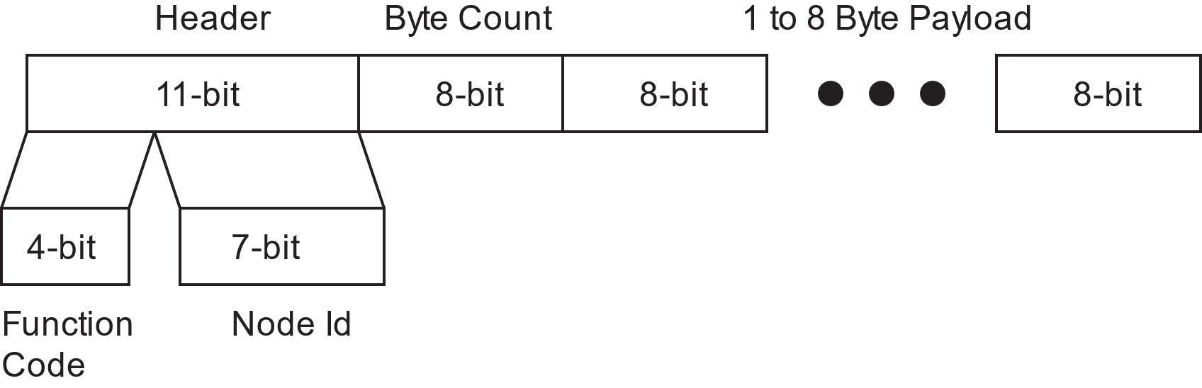
To identify frames:
- Extract Node ID:
frame.id & 0x7F - Extract TPDO type:
frame.id & 0xFF80- 0x180: Sense TPDO
- 0x280: Marker TPDO
- 0x380: Navicode TPDO
EDS File
A CANOpen Electronic Data Sheet (EDS) file is available at naviq.com for network integration.
USB Interface
The USB interface appears as a virtual COM port and supports:
- All serial commands
- PC Utility connection
- Firmware updates
- Configuration changes
- Data logging
Note: While functionally identical to RS232, USB is not recommended for permanent robot integration.