Configuration and Setup
Zero-Level Calibration
The MTS160 is calibrated at the factory. However, ambient magnetic conditions may differ at the deployment location. It is recommended to calibrate the sensor's zero level at the final installation site.
To perform zero-level calibration:
- Position the robot away from any magnetic tracks or sources
- Issue the zeroing command using one of these methods:
- Through serial command:
!ZERO - Via CAN SDO: Write to index 0x2000
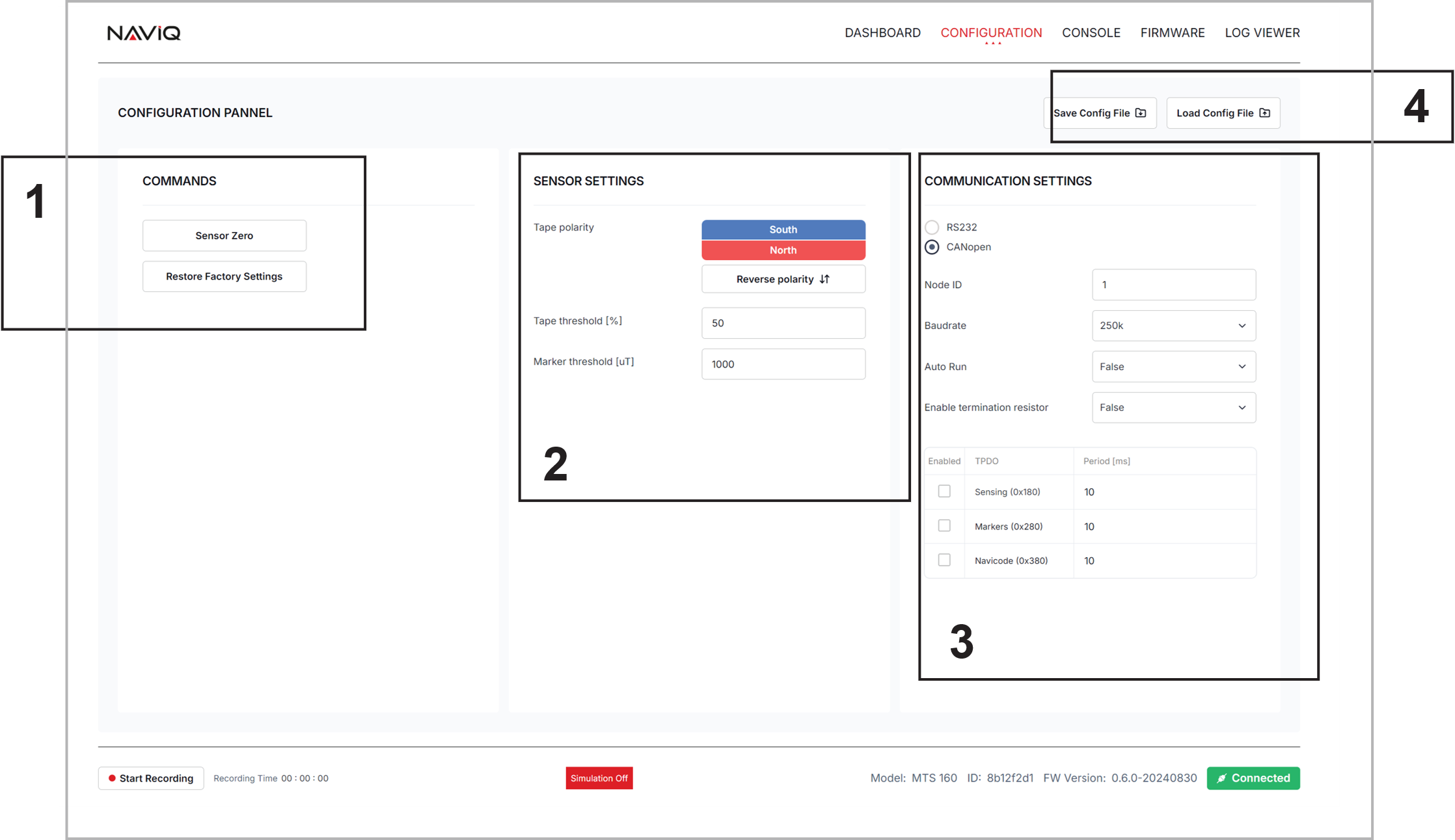
- Using the PC Utility's Configuration screen
- Through serial command:
Tape Polarity Selection
Default Configuration
By default, the sensor is configured to detect:
- Tracks: North polarity on top side
- Markers: South polarity on top side
Checking Tape Polarity
You can verify tape polarity using two methods:
String Method:
- Tie a 50-100cm string to a piece of tape
- The tape's north-facing side will align with Earth's North Pole
Compass Method:
- Hold a compass against the tape's top (non-sticky) side
- The compass's north needle is attracted to the tape's south side
- The south needle is attracted to the tape's north side
Changing Polarity Settings
Polarity can be changed through:
- Serial Command:
!SNCF,1,50,50  // For South on Top
!SNCF,0,50,50 // For North on Top- CAN SDO: Write to index 0x2002, sub-index 1:
- 0 = North on Top
- 1 = South on Top
- PC Utility: Navigate to Configuration screen and select desired polarity:

Track and Markers Threshold
The MTS160 detects tracks and markers by analyzing magnetic strength variations:
- Tracks: Detected in zones with increased magnetic strength
- Markers: Detected in zones with decreased magnetic strength

Threshold Parameters
Track Threshold:
- Defined as percentage of peak magnetic value
- Factory default: 50%
- Range: 0-100%
Marker Threshold:
- Defined in absolute milliTeslas (mT)
- Factory default: 50 mT
- Range: 0-100 mT
Adjusting Thresholds
Thresholds can be modified through:
- Serial Command:
!SNCF,[Polarity],[TrackThreshold],[MarkerThreshold]- CAN SDO:
- Track Threshold: Index 0x2002, sub-index 2
- Marker Threshold: Index 0x2002, sub-index 3
- PC Utility: Use the Configuration screen's Track and Marker Parameters section
When to Adjust Thresholds
Consider adjusting thresholds when:
- Environmental magnetic interference is present
- Magnetized steel in concrete floors affects readings
- Special application requirements need different sensitivity
Before adjusting:
- Monitor track and marker readings using PC Utility
- Analyze disturbance patterns
- Test new threshold values in controlled conditions
TIP
Factory defaults are optimized for most applications. Adjust thresholds only when necessary. If you have issues with magnetic distubances, try increasing the track threshold up to 80%.
Communication Mode Selection
The MTS160 supports multiple communication interfaces that can be configured based on system requirements.
Available Modes
RS232 Mode (Factory Default):
- Full duplex, 8 data bits, no parity, one stop bit
- No flow control
- No echo on received commands
CANOpen Mode:
- Supports up to 1Mbps
- Configurable Node ID
- Multiple TPDOs for different data types
RS232 Configuration
Configurable parameters:
Bit Rates:
- 9600 bps
- 19200 bps
- 38400 bps
- 57600 bps
- 115200 bps (Factory default)
Signal Level:
- Normal (Default)
- Inverted (for TTL compatibility)
Set via serial command:
!RSCF,[Baudrate],[Inverted]CAN Configuration
Configurable parameters:
Bit Rates:
- 125 kbps
- 250 kbps (Factory default)
- 512 kbps
- 1000 kbps
Node ID:
- Range: 1-127
- Default: 1
Additional Settings:
- Termination resistor enable/disable
- Auto-run mode
- PDO transmission periods
Set via serial command:
!CNCF,[NodeId],[Bitrate],[AutoRun],[TermResistor],[TPDO1Period],[TPDO2Period],[TPDO3Period]Using PC Utility for Configuration
- Connect sensor via USB
- Open Configuration screen
- Select Communication Protocol section
- Choose desired protocol and parameters

Saving and Loading Configurations
The PC Utility allows saving and loading configurations:
Save Configuration:
- Click "Save Config"
- Choose file location
- Configuration saved in JSON format
Load Configuration:
- Click "Load Config"
- Select previously saved file
- Configuration automatically applied
This feature is particularly useful when:
- Configuring multiple sensors identically
- Maintaining backup of working configurations
- Switching between different application requirements
Factory Reset
If needed, return to factory defaults:
- Serial Command:
!RSET- PC Utility:
- Click "Reset to Factory Defaults" button
- Confirm action when prompted
After reset, the sensor will return to:
- RS232 mode at 115200 bps
- North polarity on top
- Default thresholds (50%)
- Default CAN settings