Installation Guide
This section covers the complete installation process of the MTS160 sensor, including proper mounting procedures, electrical connections, and data connections.
Sensor Mounting
Left/Right Identification
The sensor's left and right sides are defined relative to the travel direction indicated by the arrow-shaped LED marker on the housing. The sides are also identified by the letters L and R engraved on the case.

Mounting Orientation and Height
Install the sensor in a location with minimal magnetic interference from motors, wiring, steel structures, or other magnetic sources.
Important Requirements
- Mount the sensor so that it is parallel to the floor in both the longitudinal and transverse directions.
- The recommended mounting height is 20 mm above the floor.
- Install the sensor with the M8 connector facing upward.
- For best performance, maintain a constant sensor height as the robot moves along the track.

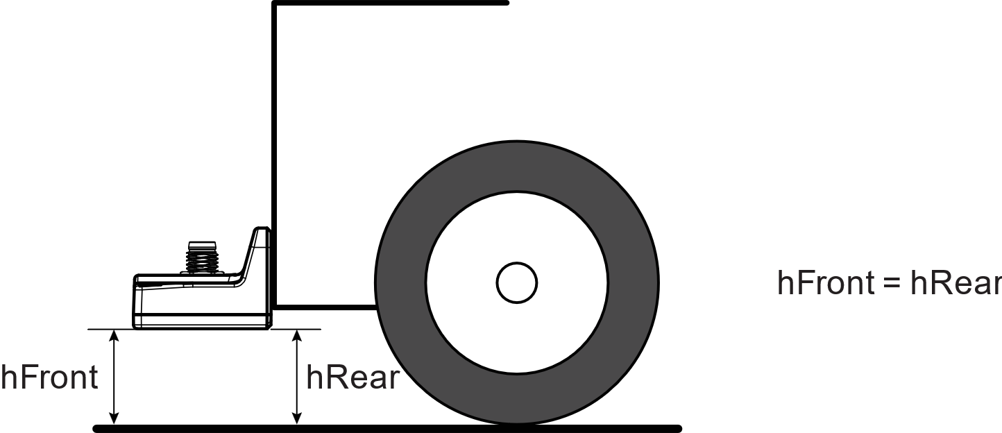
The center of the sensor should, where possible, be aligned with the centerline of the robot and mounted perpendicular to the direction of travel.

Optimal Position for Steering
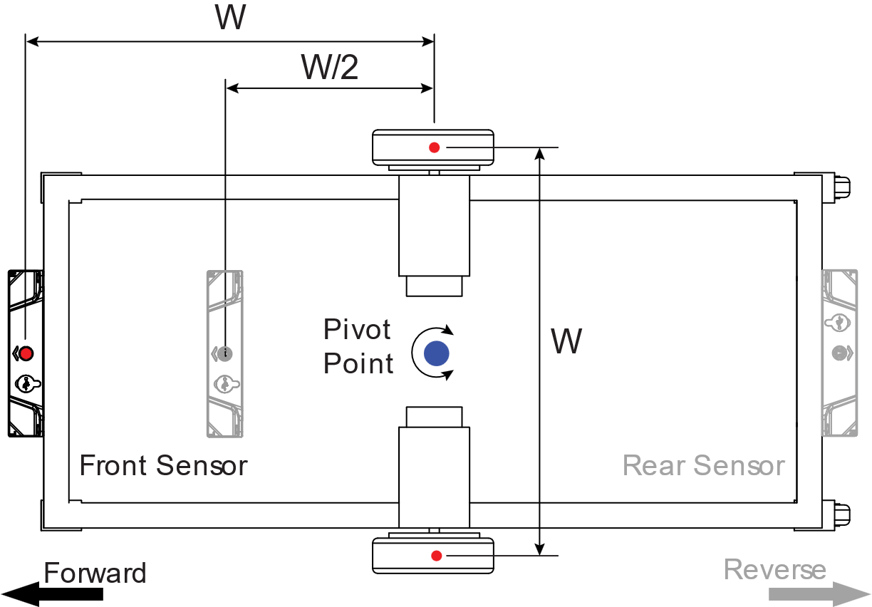
For robots with a differential-drive left/right wheel arrangement, the sensor should preferably be mounted ahead of the pivot point at a distance between W/2 and W, where W is the wheel spacing. To ensure that the robot can follow the magnetic path with precision and maintain control, the sensors should preferably be installed at a distance from the pivot point that falls between half the wheel spacing (W/2) and the full wheel spacing (W).
TIP
Mounting the sensor too close to or too far from the pivot point can make stable and accurate path-following more difficult.
For unidirectional travel, mount the sensor at the front of the vehicle. For bidirectional travel, use one sensor at the front and one at the rear.
Physical Attachment
To mount the sensor onto the robot, select an accessible area on the robot where the sensor will be attached. Refer to the dimensions indicated in the diagram and measure the spacing for the mounting holes accordingly. Mount the sensor using the two M4 mounting holes shown in Figure 8.
Position the mounting holes 18.5 mm above the desired sensing height H. Drill the holes perpendicular to the mounting surface to ensure proper alignment.
Align the sensor over the area, matching its mounting holes with those on the robot. Use M4 stainless steel screws to secure the sensor. Tighten the screws securely, but do not overtighten.
WARNING
Stainless steel is recommended to minimize the risk of magnetization that could affect sensor performance.

Electrical Connections
M8 Connector Pin Assignment


| Pin Number | Signal | Description | Wire Color |
|---|---|---|---|
| 1 | VIN+ | +7 to +28V Power Supply | Brown |
| 2 | CANH/RS232Tx | Data Signal 1 | White |
| 3 | GND | Power Supply Ground | Blue |
| 4 | CANL/RS232Rx | Data Signal 2 | Black |
Connecting the Supply Voltage
Important Safety Notes
- The sensor must be connected to a stable voltage supply between 7V and 28V DC and capable of sourcing at least 2W power.
- Always use the system's main power switch to turn the sensor on or off.
- Do not connect or disconnect the M8 connector while power is applied. Connect the cable first, then apply power.
Note
If no power is present on the M8 connector, the sensor can be powered through the USB port when connected to a PC or smartphone.
Data Connections
Data Pin Assignment
The MTS160 features a unique multi-interface, multi-protocol communication port that uses only two shared pins on the 4-pin connector. The active interface and protocol are software-selectable.

CAN Connection
The sensor allows for seamless integration with a CAN network by routing the CAN-High and CAN-Low signals to the two signal pins on the M8 connector.
The sensor includes a built-in, software-selectable 120-ohm termination resistor. It is disabled by default.
If the internal termination resistor is disabled, external 120-ohm terminators should be installed at both ends of the CAN bus.
RS232 Connection
When RS232 communication is selected, the RS232 Tx and Rx signals are routed to the two signal pins of the connector.
To communicate with another RS232 device, connect Tx, Rx, and GND accordingly.
USB Connection
The sensor can be connected directly to a PC or smartphone through its USB-C port located next to the M8 connector. When connected, it appears to the host as a serial communication port.
The USB port is intended primarily for configuration, testing, tuning, and firmware updates using the Naviq utility.
Although USB provides the same command interface as RS232, it is not recommended as the primary communication interface to the navigation controller.