CAN Communication
The MTS160 supports CANopen, allowing integration with navigation controllers, motor drives, PLCs, and other devices on a CAN bus.
TPDO Communication
The MTS160 transmits sensor data using up to three Transmit Process Data Objects (TPDOs). Each TPDO carries a different class of information and can be enabled or disabled independently.
A TPDO is transmitted when it is enabled and its configured transmission period is nonzero. Through the CANopen event-timer SDO (0x1800:5, 0x1801:5, or 0x1802:5), writing a nonzero period enables the corresponding TPDO and writing 0 disables it. Through the serial CNCF command, both the TPDO enable field and the period field must be set.
Valid period values are 0 to 65535 ms. Sensor measurements are generated every 5 ms, so TPDO periods below 5 ms can repeat the same measurement sample.
Multi-byte values in TPDO payloads are transmitted little-endian, with the least significant byte first.
"Sense" TPDO
This TPDO reports the main track-following data, including left and right track position, left and right track angle, and sensor status flags. It is the primary TPDO used for real-time navigation control.
Frame Header: 0x180 + NodeID — Byte Count: 5
| Byte | Content | Type | Range |
|---|---|---|---|
| 1 | Left Position | Signed 8-bit | ±80 mm |
| 2 | Right Position | Signed 8-bit | ±80 mm |
| 3 | Left Angle | Signed 8-bit | ±90° |
| 4 | Right Angle | Signed 8-bit | ±90° |
| 5 | Status Flags | Unsigned 8-bit | See below |
Status Flags Byte Detail:
| Bit 7 | Bit 6 | Bit 5 | Bit 4 | Bit 3 | Bit 2 | Bit 1 | Bit 0 |
|---|---|---|---|---|---|---|---|
| Merge Detect | Fork Detect | Intersection Detect | Right Marker Detect | Left Marker Detect | Track Detect & Strength | Track Detect & Strength | Unused (0) |
Track position and angle values are signed 8-bit integers. The two Track Detect & Strength bits use the same encoding as the serial SALL TDet field: 0 = no tape, 1 = weak, 2 = medium, 3 = strong. Bit 0 is unused in current firmware and is transmitted as 0.
The fork, merge, and intersection bits are implemented in current firmware. Treat them as advisory feature flags derived from magnetic geometry and validate them on the actual tape layout before using them for route decisions.
"Marker" TPDO
The "Marker" TPDO delivers precise lateral and longitudinal position data related to point-source markers. This information is critical for last-millimeter positioning.
Frame Header: 0x280 + NodeID — Byte Count: 8
| Bytes | Content | Type |
|---|---|---|
| 1-2 | Left Marker X Position (LSB, MSB) | Signed 16-bit |
| 3-4 | Left Marker Y Position (LSB, MSB) | Signed 16-bit |
| 5-6 | Right Marker X Position (LSB, MSB) | Signed 16-bit |
| 7-8 | Right Marker Y Position (LSB, MSB) | Signed 16-bit |
Position values are signed 16-bit values in tenths of a millimeter (e.g., −235 = −23.5 mm).
When no guide tape is present, a standalone point-source magnet is commonly reported as both left and right marker detections at the same lateral position.
"Navicode" TPDO
This TPDO reports the presence and value of Navicode Markers, allowing for the detection and decoding of these localization markers along a navigation path.
Frame Header: 0x380 + NodeID — Byte Count: 3
| Byte | Content | Type | Range |
|---|---|---|---|
| 1-2 | Navicode (LSB, MSB) | Unsigned 16-bit | 0–65535 |
| 3 | Counter | Unsigned 8-bit | 0–255 |
Counter is incremented every time a new Navicode is detected and captured. Navicode decoding requires markers alongside a detected guide tape; standalone point-source markers without tape do not update this TPDO.
Auto-Run Automatic TPDO Transmission
When Auto Run is enabled, the sensor enters CANopen operational state at power-up and begins transmitting enabled TPDOs. Heartbeat messages are transmitted whenever the heartbeat period is nonzero.
When Auto Run is disabled, the sensor starts in CANopen pre-operational state and waits for network control before transmitting TPDOs. If the heartbeat period is nonzero, heartbeat messages are still transmitted in pre-operational state.
SDO Objects
The MTS160 sensor supports a set of Service Data Objects (SDOs) that allow for parameter setting and sensor configuration.
SDO writes update the active configuration in RAM. To make changes survive a power cycle, save the configuration through the Naviq utility or by sending the serial !SAVE command over USB or RS232.
Zero Setting
Starts zero-level calibration of the internal magnetic sensors. This should be performed after installation and before normal operation.
| Index | Sub | Name | Type | Access |
|---|---|---|---|---|
| 0x2000 | — | ZERO | Unsigned 8-bit | Write Only |
Perform Self-Test
Starts the internal magnetic sensing self-test. This command can be used to force a self-test at any time while the sensor is powered.
| Index | Sub | Name | Type | Access |
|---|---|---|---|---|
| 0x2001 | — | SELFTEST | Unsigned 8-bit | Write Only |
Track and Marker Parameters
This SDO is used to modify the first three sensor-configuration parameters exposed by the serial SNCF command.
| Index | Sub | Name | Type | Access |
|---|---|---|---|---|
| 0x2002 | 1 | TAPE POLARITY | Unsigned 8-bit | Read/Write |
| 0x2002 | 2 | TAPE PULSE THRESHOLD | Unsigned 8-bit | Read/Write |
| 0x2002 | 3 | MARKER THRESHOLD | Unsigned 16-bit | Read/Write |
Tape polarity values are 0 for tape north on top and marker south on top, or 1 for tape south on top and marker north on top. Tape pulse threshold is a percentage of the detected tape peak. Marker threshold is in microtesla.
Read Self-Test Results
This SDO provides the results of the most recent self-test, whether performed automatically at power-up or started by the user. It returns the test result together with the minimum and maximum magnetic delta measured across the internal sensing ICs.
| Index | Sub | Name | Type | Access |
|---|---|---|---|---|
| 0x2003 | 1 | SELFTEST RESULT | Unsigned 8-bit | Read Only |
| 0x2003 | 2 | MIN MAGNETIC DELTA | Unsigned 16-bit | Read Only |
| 0x2003 | 3 | MAX MAGNETIC DELTA | Unsigned 16-bit | Read Only |
Self-test result is 1 for pass and 0 for fail. Minimum and maximum magnetic delta values are in microtesla.
Heartbeat
The sensor supports the standard CANopen heartbeat mechanism. The heartbeat interval can be set from 0 to 65535 ms. The factory-default heartbeat interval is 1000 ms. A value of 0 disables heartbeat transmission. For any nonzero setting below 100 ms, the firmware uses a 100 ms heartbeat interval.
Using the Sensor without CANopen
The sensor can be easily operated by Navigation Computers with a CAN interface, even if they do not have a full CANopen Protocol Stack.
To achieve this, enable and set the send rate for the desired TPDO(s) and activate the Auto-Run feature using the Naviq Utility. With Auto-Run enabled, the sensor will start sending the TPDOs and heartbeat at the specified rate, regardless of any other activity on the CAN network.
The data can then be captured and parsed using C or Python code on the navigation computer. Most CAN drivers will store the complete incoming frame, which is structured as follows:
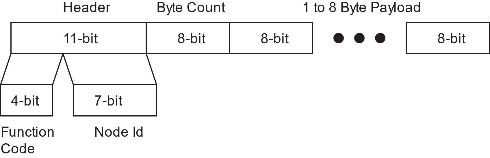
The parsing program first analyzes the header. Performing a bitwise AND operation with 0x7F will isolate the Node ID, which must then be compared with the sensor's Node ID to verify if the frame originated from the MTS160 sensor.
If this is the case, the upper part of the header should be isolated by performing a bitwise AND operation with 0xFF80. It should then be compared with 0x180, 0x280, and 0x380 to determine whether the frame contains TPDO1, TPDO2, or TPDO3.
The payload is then parsed according to the corresponding TPDO mapping described earlier in this manual.
TIP
Sample code can be obtained from the Naviq website.
CANopen EDS File
The Electronic Data Sheet (EDS) file for the MTS160 Magnetic Guide Sensor is provided to facilitate integration into a CANopen network. Containing information such as communication parameters and device-specific settings, the EDS file is necessary for proper configuration and operation within the network. It can be downloaded from the Resources section on the Naviq website at naviq.com.